
作者: aazz 時間: 2018-4-21 10:52 標題: 無擦MOTOR 的電變易不易自己整到
如淘寶這類
https://item.taobao.com/item.htm ... _1006:1110247912:N:电调:c0c2f7efe0fa8be3b83a45745e9b7fe8&ali_trackid=1_c0c2f7efe0fa8be3b83a45745e9b7fe8&spm=a230r.1.14.11#detail
作者: aazz 時間: 2018-4-21 14:15
是不是一要用 MCU;
或者編程ROM 先做到;
THANKS
作者: 燕飛 時間: 2018-4-21 15:15
是不是一要用 MCU;
或者編程ROM 先做到;
THANKS
aazz 發表於 2018-4-21 14:15

無刷無記錯要改極性/電壓 來旋轉rotor
via HKEPC Reader for Android
作者: uvvvvw 時間: 2018-4-21 16:13
這個不錯。
https://www.youtube.com/watch?v=W9IHEqlGG1s
作者: Brainstomer 時間: 2018-4-21 16:32
提示: 作者被禁止或刪除 內容自動屏蔽
作者: aazz 時間: 2018-4-21 21:22
Bridge driver整得嚟,買會簡單啲。 推MOSFET要搞上下橋,零件唔係太少。
Brainstomer 發表於 2018-4-21 16:32
這個小第知;
買應該平過自己整;
但小第手上有一些零件;
看看夠不夠零件整;
或者不須用錢另買零件;
MOSFET 小第有一些;
IRF630,540.........
作者: aazz 時間: 2018-4-21 21:32
這個不錯。
uvvvvw 發表於 2018-4-21 16:13
人兄
這套片小第看過;
但這套線路有一粒 L6234 唔平;
不過
THANKS
作者: uvvvvw 時間: 2018-4-21 21:40
回覆 7# aazz
如果做下實驗,用L298module都唔錯。十蚊人仔。
https://detail.tmall.com/item.ht ... e27b&abbucket=8
用Arduino簡化sin wave 去推都OK架。
作者: aazz 時間: 2018-4-21 22:44
本帖最後由 aazz 於 2018-4-21 22:47 編輯
回覆 aazz
如果做下實驗,用L298module都唔錯。十蚊人仔。
用Arduino簡化sin wave 去推都OK架。 ...
uvvvvw 發表於 2018-4-21 21:40
小第有幾塊 Arduino
同有 L298套件;
但造唔到這效果;
我跟這片造過;
https://www.youtube.com/watch?v=WDrRPRUpvgg
但效果一般;
起動慢至快;
但按一停 MOTOR 就起唔返;
而且控制不到轉速
作者: Brainstomer 時間: 2018-4-21 22:47
提示: 作者被禁止或刪除 內容自動屏蔽
作者: uvvvvw 時間: 2018-4-21 23:35
回覆 9# aazz
呢個係用L298嘅例子。 用查表法簡化 sin wave 的方案。
const int buttonPin1 = 4;// the number of the direction pushbutton pin
const int buttonPin2 = 5;// the number of the direction pushbutton pin
const int ledPin = 13; // the number of the status LED pin (not the flash LED)
const int motorPin1 =9; //pwm
const int motorPin2 =10; //pwm
const int motorPin3 =11; //pwm
int pwmSinA[] = {127,119,110,102,94,86,78,71,64,56,50,43,37,32,26,21,17,13,10,7,4,2,1,0,0,0,1,2,4,7,10,13,17,21,26,32,37,43,50,56,64,71,78,86,94,102,110,119,127,135,144,152,160,168,176,183,191,198,204,211,217,222,228,233,237,241,244,247,250,252,253,254,254,254,253,252,250,247,244,241,237,233,228,222,217,211,204,198,191,183,176,168,160,152,144,135}; // array of PWM duty values for 8-bit timer - sine function
int pwmSinB[] = {237,241,244,247,250,252,253,254,254,254,253,252,250,247,244,241,237,233,228,222,217,211,204,198,191,183,176,168,160,152,144,135,127,119,110,102,94,86,78,71,64,56,50,43,37,32,26,21,17,13,10,7,4,2,1,0,0,0,1,2,4,7,10,13,17,21,26,32,37,43,50,56,64,71,78,86,94,102,110,119,127,135,144,152,160,168,176,183,191,198,204,211,217,222,228,233}; // array of PWM duty values for 8-bit timer - sine function
int pwmSinC[] = {17,21,26,32,37,43,50,56,64,71,78,86,94,102,110,119,127,135,144,152,160,168,176,183,191,198,204,211,217,222,228,233,237,241,244,247,250,252,253,254,254,254,253,252,250,247,244,241,237,233,228,222,217,211,204,198,191,183,176,168,160,152,144,135,127,119,110,102,94,86,78,71,64,56,50,43,37,32,26,21,17,13,10,7,4,2,1,0,0,0,1,2,4,7,10,13}; // array of PWM duty values for 8-bit timer - sine function
const int motorDelay=300; //controls the RPM
int direction = 1; // direction 1=cw, 0=ccw
int currentStep=0;
///////////////////////////////////////////////////////////////////////////////////
void setup() {
pinMode(buttonPin1, INPUT);
digitalWrite(buttonPin1, HIGH); //internal pull up resistor
pinMode(buttonPin2, INPUT);
digitalWrite(buttonPin2, HIGH); //internal pull up resistor
pinMode(ledPin, OUTPUT);
digitalWrite(ledPin, LOW);
pinMode(motorPin1, OUTPUT);
pinMode(motorPin2, OUTPUT);
pinMode(motorPin3, OUTPUT);
//
move();
delay(100);
}//end setup()
//////////////////////////////////////////////////////////////////////////////////
//
//
//
/////////////////////////////////////////////////////////////////////////////////////////////////////
void loop()
{
if (digitalRead(buttonPin1) == LOW)
{
currentStep++;
if (currentStep > 95) currentStep=0;
move();
}
if (digitalRead(buttonPin2) == LOW)
{
currentStep--;
if (currentStep < 0) currentStep=95;
move();
}
delay(motorDelay);
}//end loop()
///////////////////////////////////////////////////////////////////////////////////////////////////
//
//
//
////////////////////////////////////////////////////////////////////////
void move()
{
analogWrite(motorPin1, pwmSinA[currentStep]);
analogWrite(motorPin2, pwmSinB[currentStep]);
analogWrite(motorPin3, pwmSinC[currentStep]);
}//end move()
////////////////////////////////////////////////////////////////////////
作者: aazz 時間: 2018-4-21 23:50
回覆 aazz
呢個係用L298嘅例子。 用查表法簡化 sin wave 的方案。
const int buttonPin1 = 4;// the nu ...
uvvvvw 發表於 2018-4-21 23:35
thanks
試試
作者: aazz 時間: 2018-4-22 08:58
小第都有 L293D 板;
https://item.taobao.com/item.htm ... &id=35550173132
但返效果都是麻麻;
十分難起動;
而且293D 在運行時十分熱;
怕佢會燒
作者: marlin12 時間: 2018-4-22 12:36
回覆 aazz
呢個係用L298嘅例子。 用查表法簡化 sin wave 的方案。
uvvvvw 發表於 2018-4-21 23:35
師兄,我係唔識控制[無刷電機]。
我想問吓點解要用sine wave去控制?點解有師兄話起動有困難?應該怎樣起動?另外,是否可以用vector control去分開控制[轉速]和[扭力]?
可否指教一吓? 謝謝!
作者: aazz 時間: 2018-4-22 12:44
本帖最後由 aazz 於 2018-4-22 12:46 編輯
師兄,我係唔識控制[無刷電機]。
我想問吓點解要用sine wave去控制?點解有師兄話起動有困難?應該怎樣起動? ...
marlin12 發表於 2018-4-22 12:36
人兄
英文小第不太懂的;
我試左找左幾個月;
找左很多 youtube片;
好像多數要用 MCU 板 或程式ROM控制;
多數是方波;
先可以又快有有力;
但小第找到的線路同 用 Arduino 去控制;
都只能起動慢;
轉速不高又沒什麼力度;
所以問問這處的人兄;
作者: uvvvvw 時間: 2018-4-22 13:50
小第都有 L293D 板;
但返效果都是麻麻;
十分難起動;
而且293D 在運行時十分熱;
怕佢會燒 ...
aazz 發表於 2018-4-22 08:58
你用嘅module可能是低電流嘅。又冇散熱。可能唔夠力。
作者: uvvvvw 時間: 2018-4-22 13:58
師兄,我係唔識控制[無刷電機]。
我想問吓點解要用sine wave去控制?點解有師兄話起動有困難?應該怎樣起動? ...
marlin12 發表於 2018-4-22 12:36
用 sine wave 控制,摩打轉得柔順D。唔會跳下跳下。
呢個係唔用 sine wave 控制嘅基礎版。可以先玩下呢個。
const int buttonPin1 = 4;// the number of the direction pushbutton pin
const int buttonPin2 = 5;// the number of the direction pushbutton pin
const int ledPin = 13; // the number of the status LED pin (not the flash LED)
const int motorAPin1 =3;
const int motorAPin2 =5;
const int motorAPin3 =6;
const int motorBPin1 =9;
const int motorBPin2 =10;
const int motorBPin3 =11;
//const int motorPins[]={3,5,6};
const int motorPinSteps[3][6]={
{1,1,1,0,0,0},
{1,0,0,0,1,1},
{0,0,1,1,1,0}};
const int motorDelay=500; // together with pot controls the RPM
boolean direct = true; // direction true=forward, false=backward
int increment;
int currentStepA=0;
///////////////////////////////////////////////////////////////////////////////////
void setup() {
pinMode(buttonPin1, INPUT);
digitalWrite(buttonPin1, HIGH); //internal pull up resistor
pinMode(buttonPin2, INPUT);
digitalWrite(buttonPin2, HIGH); //internal pull up resistor
pinMode(ledPin, OUTPUT);
digitalWrite(ledPin, LOW);
pinMode(motorAPin1, OUTPUT);
pinMode(motorAPin2, OUTPUT);
pinMode(motorAPin3, OUTPUT);
pinMode(motorBPin1, OUTPUT);
pinMode(motorBPin2, OUTPUT);
pinMode(motorBPin3, OUTPUT);
//
move();
delayMicroseconds(motorDelay);
}//end setup()
//////////////////////////////////////////////////////////////////////////////////
//
//
//
/////////////////////////////////////////////////////////////////////////////////////////////////////
void loop()
{
currentStepA++;
if (currentStepA > 5) currentStepA=0;
move();
delay( motorDelay);
}//end loop()
///////////////////////////////////////////////////////////////////////////////////////////////////
//
//
//
////////////////////////////////////////////////////////////////////////
void move()
{
digitalWrite(motorAPin1,motorPinSteps[0][currentStepA]);
digitalWrite(motorAPin2,motorPinSteps[1][currentStepA]);
digitalWrite(motorAPin3,motorPinSteps[2][currentStepA]);
digitalWrite(motorBPin1,motorPinSteps[0][currentStepA]);
digitalWrite(motorBPin2,motorPinSteps[1][currentStepA]);
digitalWrite(motorBPin3,motorPinSteps[2][currentStepA]);
}//end move()
////////////////////////////////////////////////////////////////////////
若用 Arduino 控制 ESC (electronic speed controller) ,起動先至比較複雜。
否則同控制步進馬達差唔多。只要起步速度不太快,一般沒問題。
作者: uvvvvw 時間: 2018-4-22 14:01
人兄
英文小第不太懂的;
我試左找左幾個月;
找左很多 youtube片;
好像多數要用 MCU 板 或程式ROM控制;
多 ...
aazz 發表於 2018-4-22 12:44
想快要考慮加速度。就是先慢後快。
一開始速度太快,會轉唔郁嘅。
作者: aazz 時間: 2018-4-22 15:41
想快要考慮加速度。就是先慢後快。
一開始速度太快,會轉唔郁嘅。
uvvvvw 發表於 2018-4-22 14:01
但硬碟 MOTOR 的電路;
好像一開始就是快的;
而且按停可以再轉得反;
不過力度是差一些
作者: aazz 時間: 2018-4-22 15:49
你用嘅module可能是低電流嘅。又冇散熱。可能唔夠力。
uvvvvw 發表於 2018-4-22 13:50
人兄
小第就是用上面淘寶的連結;
那塊擴展板;
作者: aazz 時間: 2018-4-22 16:16
回覆 aazz
呢個係用L298嘅例子。 用查表法簡化 sin wave 的方案。
const int buttonPin1 = 4;// the nu ...
uvvvvw 發表於 2018-4-21 23:35
人兄
你程序的 PWM 4 ,5 腳
是否是 要連接或斷開方式
可否有圖板的連線
作者: uvvvvw 時間: 2018-4-22 22:29
人兄
你程序的 PWM 4 ,5 腳
是否是 要連接或斷開方式
可否有圖板的連線
aazz 發表於 2018-4-22 16:16
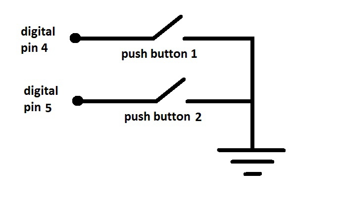
程序裡的 digital pins 4 and 5 係 push buttons (正轉及反轉) 的接囗。


 圖片附件: ss.jpg (2018-4-22 22:28, 39.15 KB) / 下載次數 73
https://www.hkepc.com/forum/attachment.php?aid=2054446&k=c972987f8675153616bd5b15aeb16135&t=1794924153&sid=1NKFFb2uZu
作者: aazz 時間: 2018-4-22 22:53
本帖最後由 aazz 於 2018-4-22 22:55 編輯
回覆 aazz
呢個係用L298嘅例子。 用查表法簡化 sin wave 的方案。
const int buttonPin1 = 4;// the nu ...
uvvvvw 發表於 2018-4-21 23:35
人兄
這幾行的 PIN 位;
9,10,11
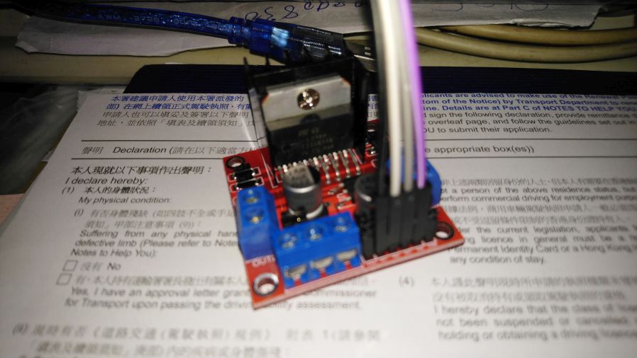
是否連下圖這個的 IN1-3;
圖片附件: DSC_0023-2.jpg (2018-4-22 22:53, 75.25 KB) / 下載次數 66https://www.hkepc.com/forum/attachment.php?aid=2054454&k=2b11bf7c0cd51f0836ad001c38f35f43&t=1794924153&sid=1NKFFb2uZu
作者: uvvvvw 時間: 2018-4-22 23:09
回覆 23# aazz
是的
作者: aazz 時間: 2018-4-23 14:16
本帖最後由 aazz 於 2018-4-23 14:19 編輯
回覆 aazz
是的
uvvvvw 發表於 2018-4-22 23:09
人兄
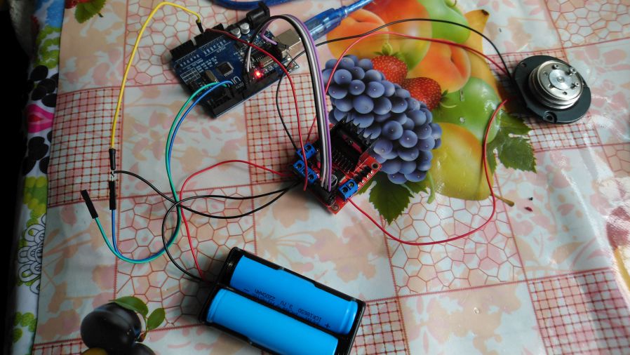
已試了;
第一個程序 完全不動;
MOTOR 磁實左;
第二個程序一格一格轉;
好慢;
幾秒就停;
這樣接線
圖片附件: DSC_0024-2.jpg (2018-4-23 14:18, 104.32 KB) / 下載次數 79https://www.hkepc.com/forum/attachment.php?aid=2054574&k=abcd4e2f02e3ce757acf312f92865180&t=1794924153&sid=1NKFFb2uZu
作者: uvvvvw 時間: 2018-4-23 14:21
人兄
已試了;
第一個程序 完全不動;
MOTOR 磁實左;
第二個程序一格一格轉;
好慢;
幾秒就停;
這樣接線 ...
aazz 發表於 2018-4-23 14:16
.可能相位次序錯了。試試將摩打其中兩條線掉轉接。
作者: aazz 時間: 2018-4-23 16:33
.可能相位次序錯了。試試將摩打其中兩條線掉轉接。
uvvvvw 發表於 2018-4-23 14:21
有空再試;
THANKS
作者: ghostkcleung 時間: 2018-4-23 17:15
本帖最後由 ghostkcleung 於 2018-4-23 17:17 編輯
當你自製完隻電變之後,
順理成章應該自製埋隻摩打。
不過我都想學吓無刷摩打原理。
作者: aazz 時間: 2018-4-23 21:26
當你自製完隻電變之後,
順理成章應該自製埋隻摩打。
不過我都想學吓無刷摩打原理。 ...
ghostkcleung 發表於 2018-4-23 17:15
人兄
小第找過很多 鷓擦摩打的片;
同線路;
和這在這裡問過各人兄;
都是一些要用 MCU , 程序 或 Arduino 先做到;
完成自制;
看來沒什麼可能;
至於無擦摩打原理;
基本上同 步進摩打一樣;
但步小很多;
相也小很多;
速度可以高很多;
扭力都可以比普通摩打大;
所以現在都有電動車用緊
而且是最新型那款
作者: ghostkcleung 時間: 2018-4-23 21:38
本帖最後由 ghostkcleung 於 2018-4-23 21:44 編輯
人兄
小第找過很多 鷓擦摩打的片;
同線路;
和這在這裡問過各人兄;
都是一些要用 MCU , 程序 或 Arduino ...
aazz 發表於 2018-4-23 21:26
我覺得電變點都應該要有 MCU 元素,
平時啲電變,要 update firmware,
有幾個基本設定 例如摩打進角,PWM frequency ,
摩打轉向…MCU 控制 MOSFET 再控制摩打。
而我最唔明係其中一個 “糟” 通電後,
將磁極吸過嚟,
之後點樣令電變知道要輪到下一個 “糟” 通電嘅時機。
作者: Brainstomer 時間: 2018-4-23 21:42
提示: 作者被禁止或刪除 內容自動屏蔽
作者: aazz 時間: 2018-4-23 22:10
睇落好似SPWM, 但gen完出嚟唔駛LC濾波先?
唔濾波簡直同短pulse無分別噃.....
早排我都玩過, drive 單極AC ...
Brainstomer 發表於 2018-4-23 21:42
小第都看過一些細四軸飛行器;
用DC 有擦摩打;
都是用一些 有STM32 來編程的 ;
ALL IN ONE 底板;
作者: uvvvvw 時間: 2018-4-23 22:47
搵翻N年前用BLDC玩機械人的板。
再Load個sketch落去試下。
重work喎。
冇用push button。稍為改下個sketch。
基礎版
=====
//const int buttonPin1 = 4;// the number of the direction pushbutton pin
//const int buttonPin2 = 5;// the number of the direction pushbutton pin
const int ledPin = 13; // the number of the status LED pin (not the flash LED)
const int motorPin1 =9;
const int motorPin2 =10;
const int motorPin3 =11;
const int motorPins[]={6,7,8};
const int motorPinSteps[3][6]={
{1,1,1,0,0,0},
{1,0,0,0,1,1},
{0,0,1,1,1,0}};
int motorDelay=8; // together with pot controls the RPM
boolean direct = true; // direction true=forward, false=backward
int increment;
int currentStepA=0;
///////////////////////////////////////////////////////////////////////////////////
void setup() {
//pinMode(buttonPin1, INPUT);
//digitalWrite(buttonPin1, HIGH); //internal pull up resistor
//pinMode(buttonPin2, INPUT);
//digitalWrite(buttonPin2, HIGH); //internal pull up resistor
pinMode(ledPin, OUTPUT);
digitalWrite(ledPin, LOW);
pinMode(motorPin1, OUTPUT);
pinMode(motorPin2, OUTPUT);
pinMode(motorPin3, OUTPUT);
//
move();
delay(300);
}//end setup()
//////////////////////////////////////////////////////////////////////////////////
//
//
//
/////////////////////////////////////////////////////////////////////////////////////////////////////
void loop()
{
currentStepA++;
if (currentStepA > 5) currentStepA=0;
move();
delay( motorDelay);
}//end loop()
///////////////////////////////////////////////////////////////////////////////////////////////////
//
//
//
////////////////////////////////////////////////////////////////////////
void move()
{
digitalWrite(motorPin1,motorPinSteps[0][currentStepA]);
digitalWrite(motorPin2,motorPinSteps[1][currentStepA]);
digitalWrite(motorPin3,motorPinSteps[2][currentStepA]);
}//end move()
////////////////////////////////////////////////////////////////////////
sine wave 版
========
//const int buttonPin1 = 4;// the number of the direction pushbutton pin
//const int buttonPin2 = 5;// the number of the direction pushbutton pin
const int ledPin = 13; // the number of the status LED pin (not the flash LED)
const int motorPin1 =9; //pwm
const int motorPin2 =10; //pwm
const int motorPin3 =11; //pwm
int pwmSinA[] = {127,119,110,102,94,86,78,71,64,56,50,43,37,32,26,21,17,13,10,7,4,2,1,0,0,0,1,2,4,7,10,13,17,21,26,32,37,43,50,56,64,71,78,86,94,102,110,119,127,135,144,152,160,168,176,183,191,198,204,211,217,222,228,233,237,241,244,247,250,252,253,254,254,254,253,252,250,247,244,241,237,233,228,222,217,211,204,198,191,183,176,168,160,152,144,135}; // array of PWM duty values for 8-bit timer - sine function
int pwmSinB[] = {237,241,244,247,250,252,253,254,254,254,253,252,250,247,244,241,237,233,228,222,217,211,204,198,191,183,176,168,160,152,144,135,127,119,110,102,94,86,78,71,64,56,50,43,37,32,26,21,17,13,10,7,4,2,1,0,0,0,1,2,4,7,10,13,17,21,26,32,37,43,50,56,64,71,78,86,94,102,110,119,127,135,144,152,160,168,176,183,191,198,204,211,217,222,228,233}; // array of PWM duty values for 8-bit timer - sine function
int pwmSinC[] = {17,21,26,32,37,43,50,56,64,71,78,86,94,102,110,119,127,135,144,152,160,168,176,183,191,198,204,211,217,222,228,233,237,241,244,247,250,252,253,254,254,254,253,252,250,247,244,241,237,233,228,222,217,211,204,198,191,183,176,168,160,152,144,135,127,119,110,102,94,86,78,71,64,56,50,43,37,32,26,21,17,13,10,7,4,2,1,0,0,0,1,2,4,7,10,13}; // array of PWM duty values for 8-bit timer - sine function
int motorDelay=400; //controls the RPM
int direction = 1; // direction 1=cw, 0=ccw
int currentStep=0;
///////////////////////////////////////////////////////////////////////////////////
void setup() {
//pinMode(buttonPin1, INPUT);
//digitalWrite(buttonPin1, HIGH); //internal pull up resistor
//pinMode(buttonPin2, INPUT);
//digitalWrite(buttonPin2, HIGH); //internal pull up resistor
pinMode(ledPin, OUTPUT);
digitalWrite(ledPin, LOW);
pinMode(motorPin1, OUTPUT);
pinMode(motorPin2, OUTPUT);
pinMode(motorPin3, OUTPUT);
//
move();
delay(100);
}//end setup()
//////////////////////////////////////////////////////////////////////////////////
//
//
//
/////////////////////////////////////////////////////////////////////////////////////////////////////
void loop()
{
currentStep++;
if (currentStep > 95) currentStep=0;
move();
delayMicroseconds(motorDelay);
}//end loop()
///////////////////////////////////////////////////////////////////////////////////////////////////
//
//
//
////////////////////////////////////////////////////////////////////////
void move()
{
analogWrite(motorPin1, pwmSinA[currentStep]);
analogWrite(motorPin2, pwmSinB[currentStep]);
analogWrite(motorPin3, pwmSinC[currentStep]);
}//end move()
////////////////////////////////////////////////////////////////////////
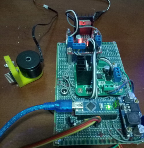
若然唔work, 可能係用嘅BLDC唔同。
試下增大 delay() 或 delayMicroseconds() 嘅值。
或者調換下接線順序。
圖片附件: P80423-222343.jpg (2018-4-23 22:37, 106.85 KB) / 下載次數 88https://www.hkepc.com/forum/attachment.php?aid=2054703&k=ec844c94fa813f54bedca7ad513f8e0c&t=1794924153&sid=1NKFFb2uZu
作者: AlfYeung 時間: 2018-4-23 23:04
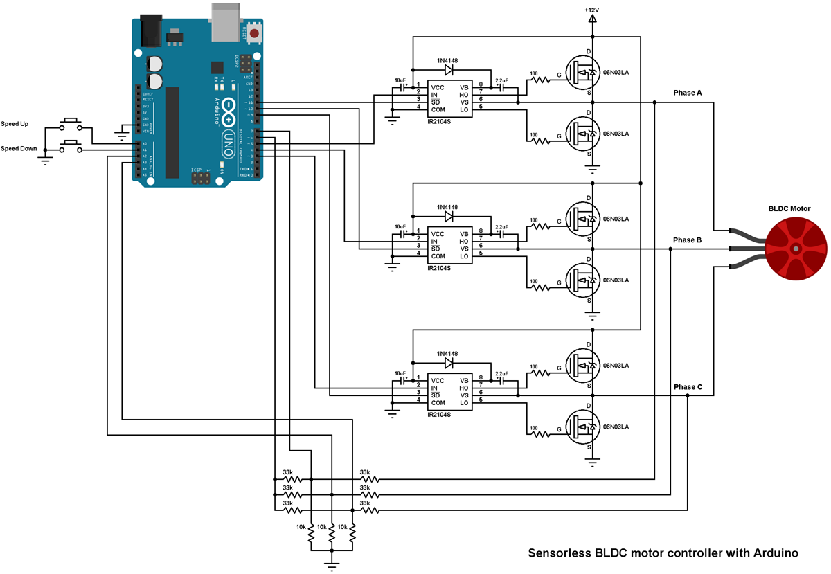
圖片附件: arduino-sensorless-brushless-dc-motor-control-diy-esc.png (2018-4-23 23:03, 130.63 KB) / 下載次數 83https://www.hkepc.com/forum/attachment.php?aid=2054708&k=e56525c6abb240a2ec6ce8575b4e6ec3&t=1794924153&sid=1NKFFb2uZu
作者: uvvvvw 時間: 2018-4-23 23:08
我覺得電變點都應該要有 MCU 元素,
平時啲電變,要 update firmware,
有幾個基本設定 例如摩打進角,PW ...
ghostkcleung 發表於 2018-4-23 21:38
如果唔用ESC,而用Arduino 或者STM控制BLDC。咁Arduino 或者STM就係MCU元素。
簡單控制,同控制步進電機差不多。前面提到的基礎版類似步進嘅整步控制。而sine wave版就類似micro step 控制。
商用BLDC控制一般用hall sensor去同步磁極的位置(例如電動單車),或者用back EMF (例如BLDC散熱扇)。最近見過用encoder嘅相機穩定器。
作者: AlfYeung 時間: 2018-4-23 23:19
https://simple-circuit.com/ardui ... tor-controller-esc/
作者: Brainstomer 時間: 2018-4-24 09:14
提示: 作者被禁止或刪除 內容自動屏蔽
作者: uvvvvw 時間: 2018-4-24 09:19
回覆 37# Brainstomer
呢個係攝影雲台穩定器用的bldc。5V都推得郁。
作者: aazz 時間: 2018-4-24 11:41
如果用square wave,我試過驅動電壓係低好多下。
樓主似乎係HDD motor,正常都要用12V。 ...
Brainstomer 發表於 2018-4-24 09:14
因為盡量節省成本;
用住HDD MOTOR 先;
整好線路 OK;
再想MOTOR
THANKS
各位再試
作者: no1chan 時間: 2018-4-24 13:05
要做 electronic commutation. 有好多野搞架

via HKEPC Reader for Android
作者: AlfYeung 時間: 2018-4-24 16:51
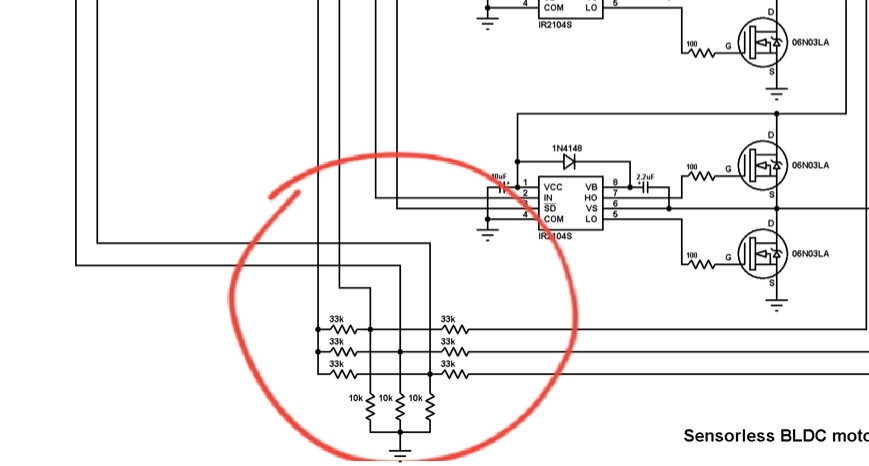
樓主開宗明義想DIY現今流行的BL ESC,那麼怎能省略detect EMF 的部分?
圖片附件: 20180424_164925.jpg (2018-4-24 16:50, 75.9 KB) / 下載次數 87https://www.hkepc.com/forum/attachment.php?aid=2054845&k=7406f3a950c45df4d96e126013d2beb9&t=1794924153&sid=1NKFFb2uZu
作者: no1chan 時間: 2018-4-24 21:40
回覆 41# AlfYeung
st 同ti 果d廠有提供library 嘅 不過好似行foc 而唔係普通電調行嘅 six-step commutation
作者: marlin12 時間: 2018-4-24 21:42
本帖最後由 marlin12 於 2018-4-24 23:02 編輯
Sensorless BLDC motor control with Arduino – DIY ESC
AlfYeung 發表於 2018-4-23 23:19
做commutation的好處,就是讓控制器可以根據[轉子]的位置,在適當的時間轉換控制波形。這樣便可以令[無刷電機]在不同的負載和干擾下,都可以順暢和有力地轉動。
我睇過佢呢個project,其實佢做得唔錯。
佢用Arduino內部comparator加上幾個電阻,便可以量度電機在轉動時產生的back EMF波形,從而得知[轉子]的位置,做到commutation。你睇返佢個程式,其實用back EMF來做commutation,並不複雜。
因為電機要達到某個速度,才能產生有效的back EMF。因此,佢將電機起動到某個速度以上,才開始做commutation。
做咗commutation之後,佢就用PWM來控制加到[無刷電機]的平均電壓,以達到控制速度的目的。
作者: AlfYeung 時間: 2018-4-25 09:01
雖然未試過DIY ESC,但試過改ESC firmware。首先要跟線,才知道三個通道的上、下FET分別用哪個port、羅輯電平來控制。因此對電路少少認知,先前上傳的圖跟巿售的ESC極為相似,值得彷效。如果移植埋最流行的BLHeli firmware 就無敵!
作者: aazz 時間: 2018-4-25 10:09
雖然未試過DIY ESC,但試過改ESC firmware。首先要跟線,才知道三個通道的上、下FET分別用哪個port、羅輯電 ...
AlfYeung 發表於 2018-4-25 09:01
可惜個線路有幾粒IC 要另外買;
香港買不平;
手上又沒有這個型號 MOSFET
作者: aazz 時間: 2018-4-25 10:10
剛找到這個;
剛試又OK;
可以控制慢同快;
但快就不是十分快;
https://www.youtube.com/watch?v=r_iyW9dIqqQ
http://wvs-k.weebly.com/sinus-3phase-pwm-arduino.html
作者: AlfYeung 時間: 2018-4-25 10:45
我的想法是保留L298做推動,同時加 detect EMF 來控制換相。只有精確的換相才能改善速度及轉矩。
作者: aazz 時間: 2018-4-25 10:51
搵翻N年前用BLDC玩機械人的板。
再Load個sketch落去試下。
重work喎。
冇用push button。稍為改下個sketch ...
uvvvvw 發表於 2018-4-23 22:47
人兄
好神奇;
今早剛試這兩個程序都沒問題;
可以轉到;
而且按停 MOTOR 都可以起動返
不過就幾慢
作者: aazz 時間: 2018-4-25 10:53
我的想法是保留L298做推動,同時加 detect EMF 來控制換相。只有精確的換相才能改善速度及轉矩。 ...
AlfYeung 發表於 2018-4-25 10:45
但要買到這三顆IC 才能試;
這個電路了;
THANKS
作者: uvvvvw 時間: 2018-4-25 11:25
人兄
好神奇;
今早剛試這兩個程序都沒問題;
可以轉到;
而且按停 MOTOR 都可以起動返
不過就幾慢 ...
aazz 發表於 2018-4-25 10:51
我估要快就一定要用有feed back 嘅方法嘞。
作者: aazz 時間: 2018-4-25 11:28
我估要快就一定要用有feed back 嘅方法嘞。
uvvvvw 發表於 2018-4-25 11:25
什麼叫 Feed back 方法呢;
THANKS
作者: aazz 時間: 2018-4-25 11:36
我估要快就一定要用有feed back 嘅方法嘞。
uvvvvw 發表於 2018-4-25 11:25
這個 VIDEO 寫可以上 4000RPM;
小第試過都幾快;
但唔夠用硬碟底板快;
而且要由慢;
慢慢轉快;
如果唔係會停;
停左起動不到
https://www.youtube.com/watch?v=WDrRPRUpvgg
作者: uvvvvw 時間: 2018-4-25 12:02
什麼叫 Feed back 方法呢;
THANKS
aazz 發表於 2018-4-25 11:28
back EMF 彧hall sensor 等
要快重要考慮加速度。即係起步時慢慢增加速度。
btw,硬碟摩打慣性細,對加速要求無咁高。
作者: aazz 時間: 2018-4-25 12:15
本帖最後由 aazz 於 2018-4-25 12:17 編輯
back EMF 彧hall sensor 等
要快重要考慮加速度。即係起步時慢慢增加速度。
btw,硬碟摩打慣性細,對加速要 ...
uvvvvw 發表於 2018-4-25 12:02
是不是位置檢測;
同 回饋控制
硬碟MOTOR 只是暫時測試用;
作者: AlfYeung 時間: 2018-4-25 12:27
但要買到這三顆IC 才能試;
這個電路了;
THANKS
aazz 發表於 2018-4-25 10:53
我想講唔使加IC,只加幾粒電阻,同改CODE,做EMF detect 試吓先。
作者: AlfYeung 時間: 2018-4-25 12:31
條片都無機度轉數,話4萬轉都得啦。
作者: aazz 時間: 2018-4-25 12:33
我想講唔使加IC,只加幾粒電阻,同改CODE,做EMF detect 試吓先。
AlfYeung 發表於 2018-4-25 12:27
OK
又試試先
THANKS
作者: marlin12 時間: 2018-4-25 20:23
本帖最後由 marlin12 於 2018-4-26 19:52 編輯
回覆 AlfYeung
st 同ti 果d廠有提供library 嘅 不過好似行foc 而唔係普通電調行嘅 six-step commutati ...
no1chan 發表於 2018-4-24 21:40
FOC是vector control,可以分別控制轉速和扭力,有很好的動態反應,主要用在負載不斷變化的應用(例如:洗衣機、冷氣機、電動車)。不少廠商的應用方案,都是針對[家電]這個龐大市場。
因為FOC要做[實時]的Clarke和Park transform/inverse transform,需要用上高速的DSP運算能力,非一般的MCU可以處理。
如果電機負載不會在同一周期內變化(例如:風扇、轉台等應用),用scalar control(即是你所講的six-step commutation)便可以應付。
作者: aazz 時間: 2018-4-27 09:43
本帖最後由 aazz 於 2018-4-27 09:51 編輯
這個程式是否可以更改 頻率來增加速度呢;
typedef unsigned char PROGMEM prog_uchar;
// table of 256 sine values / one sine period / stored in flash memory
PROGMEM prog_uchar const sine256[] = {
127,130,133,136,139,143,146,149,152,155,158,161,164,167,170,173,176,178,181,184,187,190,192,195,198,200,203,205,208,210,212,215,217,219,221,223,225,227,229,231,233,234,236,238,239,240,
242,243,244,245,247,248,249,249,250,251,252,252,253,253,253,254,254,254,254,254,254,254,253,253,253,252,252,251,250,249,249,248,247,245,244,243,242,240,239,238,236,234,233,231,229,227,225,223,
221,219,217,215,212,210,208,205,203,200,198,195,192,190,187,184,181,178,176,173,170,167,164,161,158,155,152,149,146,143,139,136,133,130,127,124,121,118,115,111,108,105,102,99,96,93,90,87,84,81,78,
76,73,70,67,64,62,59,56,54,51,49,46,44,42,39,37,35,33,31,29,27,25,23,21,20,18,16,15,14,12,11,10,9,7,6,5,5,4,3,2,2,1,1,1,0,0,0,0,0,0,0,1,1,1,2,2,3,4,5,5,6,7,9,10,11,12,14,15,16,18,20,21,23,25,27,29,31,
33,35,37,39,42,44,46,49,51,54,56,59,62,64,67,70,73,76,78,81,84,87,90,93,96,99,102,105,108,111,115,118,121,124
};
#define cbi(sfr, bit) (_SFR_BYTE(sfr) &= ~_BV(bit))
#define sbi(sfr, bit) (_SFR_BYTE(sfr) |= _BV(bit))
int PWM_OUT_U =11;
int PWM_OUT_V =10;
int PWM_OUT_W = 9;
int LED_PIN =13; // LED status on pin 13
int TEST_PIN =7; // Scope trigger on pin 7
int OFFSET_V =85; // Offset for second-phase
int OFFSET_W =170; // Offset for third-phase
int dfmax =115;
int dfm =1;
int doonce=0;
int analog_val= 0;
double dfreq,dfreq_old;
const double refclk=31372.549 ;
//const double refclk = 31376.6; // measured
const uint64_t twoTo32 = pow(2, 32); // compute value at startup and use as constant
// variables used inside interrupt service declared as voilatile
volatile uint8_t icnt; // var inside interrupt
volatile uint8_t icnt1; // var inside interrupt
volatile uint8_t c4ms; // counter incremented every 4ms
volatile uint32_t phase_accum; // pahse accumulator
volatile uint32_t tword_m; // dds tuning word m
//******************************************************************
void setup()
{
pinMode(LED_PIN, OUTPUT); // sets the digital pin as output
Serial.begin(115200); // connect to the serial port
Serial.println("DDS Test");
pinMode(TEST_PIN, OUTPUT); // sets the digital pin as output
pinMode(PWM_OUT_U, OUTPUT); // PWM output / frequency output
pinMode(PWM_OUT_V, OUTPUT); // PWM output / frequency output
pinMode(PWM_OUT_W, OUTPUT); // PWM output / frequency output
// Setup the timers
setup_timer1();
setup_timer2();
// disable interrupts to avoid timing distortion
cbi (TIMSK0, TOIE0); // disable Timer0 !!! delay() is now not available
sbi (TIMSK2, TOIE2); // enable Timer2 Interrupt
dfreq = 0.0; // initial output frequency = 1000.0 Hz
tword_m = twoTo32 * dfreq / refclk; // calulate DDS new tuning word
}
//******************************************************************
void loop()
{
/*
if (!doonce) {
dfreq=map(analogRead(0),0,1023,0,800);
dfreq_old=dfreq;
}
if(abs(dfreq-dfreq_old )> 10) {
if(dfreq>dfreq_old ) dfreq+=10;
else dfreq-=10;
doonce=1;
} else doonce=0;
/ */
/*
dfmax=map(analogRead(0),0,1023,0,800);
if (dfreq == 0){ dfm = 10;} // run up an down xHz each second
if (dfreq >= dfmax){ dfm = -10;}
dfreq+= dfm;
*/
analog_val=analogRead(0);
dfreq=map(analog_val,0,1023,0,100);
// read Poti on analog pin 0 -- 716 = 4.24V = 103 Hz
if (c4ms > 250) // timer / wait for a full second
{
c4ms = 0;
cbi (TIMSK2, TOIE2); // disble Timer2 Interrupt
tword_m = twoTo32 * dfreq / refclk; // calulate DDS new tuning word
sbi (TIMSK2, TOIE2); // enable Timer2 Interrupt
Serial.print(analog_val);
Serial.print(" ");
Serial.print(dfreq);
Serial.print(" ");
Serial.print(dfmax);
Serial.print(" ");
Serial.println(tword_m);
}
}
//******************************************************************
// timer1 setup
// set prscaler to 1, PWM mode to phase correct PWM, 16000000/512 = 31.25kHz clock
void setup_timer1(void)
{
// Timer1 Clock Prescaler to : 1
sbi (TCCR1B, CS10);
cbi (TCCR1B, CS11);
cbi (TCCR1B, CS12);
// Timer0 PWM Mode set to Phase Correct PWM
cbi (TCCR1A, COM1A0); // clear Compare Match
sbi (TCCR1A, COM1A1);
cbi (TCCR1A, COM1B0); // clear Compare Match
sbi (TCCR1A, COM1B1);
sbi (TCCR1A, WGM10); // Mode 1 / Phase Correct PWM
cbi (TCCR1A, WGM11);
cbi (TCCR1B, WGM12);
cbi (TCCR1B, WGM13);
}
//******************************************************************
// timer2 setup
// set prscaler to 1, PWM mode to phase correct PWM, 16000000/512 = 31.25kHz clock
void setup_timer2()
{
// Timer2 Clock Prescaler to : 1
sbi (TCCR2B, CS20);
cbi (TCCR2B, CS21);
cbi (TCCR2B, CS22);
// Timer2 PWM Mode set to Phase Correct PWM
cbi (TCCR2A, COM2A0); // clear Compare Match
sbi (TCCR2A, COM2A1);
sbi (TCCR2A, WGM20); // Mode 1 / Phase Correct PWM
cbi (TCCR2A, WGM21);
cbi (TCCR2B, WGM22);
}
//******************************************************************
// Timer2 Interrupt Service at 31.25kHz = 32us
// this is the timebase REFCLOCK for the DDS generator
// FOUT = (M (REFCLK)) / (2 exp 32)
// runtime : 8 microseconds ( inclusive push and pop)
ISR(TIMER2_OVF_vect)
{
if (!icnt || icnt==127){
sbi(PORTD, TEST_PIN); // Test / set PORTD,TEST_PIN high to observe timing with a oscope
}
phase_accum += tword_m; // soft DDS, phase accu with 32 bits
icnt = phase_accum >> 24; // use upper 8 bits for phase accu as frequency information
OCR2A = pgm_read_byte_near(sine256 + icnt); // read value fron ROM sine table and send to PWM DAC
OCR1A = pgm_read_byte_near(sine256 + (uint8_t)(icnt + OFFSET_V));
OCR1B = pgm_read_byte_near(sine256 + (uint8_t)(icnt + OFFSET_W));
if (icnt1++ == 125) // increment variable c4ms every 4 milliseconds
{
c4ms++;
icnt1 = 0;
}
if (!icnt || icnt==127){
cbi(PORTD, TEST_PIN); // reset PORTD,TEST_PIN
}
}
https://www.youtube.com/watch?v=r_iyW9dIqqQ
http://wvs-k.weebly.com/sinus-3phase-pwm-arduino.html
作者: Brainstomer 時間: 2018-4-27 13:06
提示: 作者被禁止或刪除 內容自動屏蔽
作者: aazz 時間: 2018-4-27 13:47
呢個係SPWM嘅code,一改頻率,就需要依賴external program去計過所有value。
如果純粹推摩打,用普通PWM ...
Brainstomer 發表於 2018-4-27 13:06
thanks